
Guide for Dimensioning a Piezo Stack Actuator System
The comparison of the application requirements with key performance data of Piezotechnik stack actuators can provide a first feasibility check of an envisaged piezo actuator application.
The two most important key performance indictors of piezo stack actuator are stroke and force. These data are directly related with the size of the stack:
- The strong force generation capability is proportional to the base area of the stack.
- The displacement capability is proportional to the length of the stack.
- Fast response require sufficient power amplifier current.
- Precise reaction requires dedicated control system.
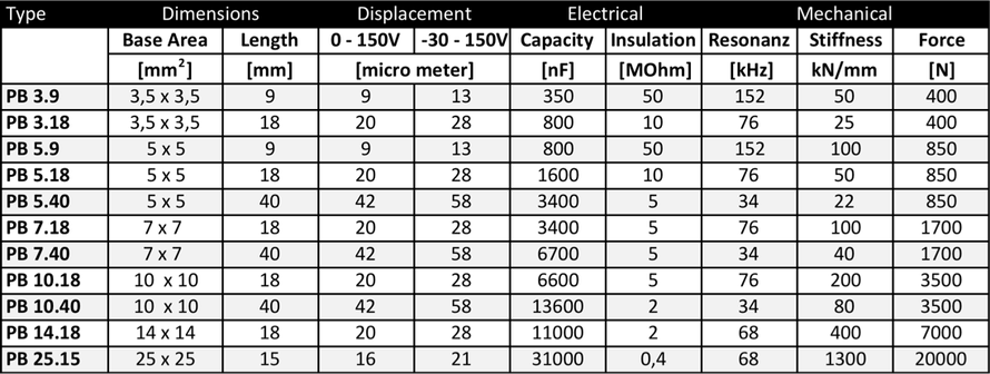
The capacity C and the maximum operating voltage U are the key electrical data and is directly related with the size of the stack. In the following table key data are summarized and represent the range of actuator stacks.
|
Symbol |
Meaning |
Minimum |
Maximum |
Special Design |
|
X |
displacement |
2 µm |
100 µm |
1 µm - 400 µm |
|
Fb |
blocking force |
200 N |
4 kN |
50 kN |
|
A |
base area |
2 x 3mm2 |
10 x10 mm2 |
25 kN |
|
s |
active stress |
3500N/cm2 |
|
|
|
S |
active strain |
0,1% |
0,2% |
|
|
L |
length |
2 mm |
100mm |
1 mm, 400 mm |
|
C |
capacity |
typ. 3 mF/cm3 per active stack volume |
|
|
|
U |
voltage |
-30 to +150 V |
0 to 150 V |
300 V, 600 V |
|
T |
temperature |
-25 oC |
+ 85 oC |
cryo |
|
rH |
humidity |
< 60% rH |
100% |
|
To start with the design, consider the standard actuator program as a first reference and compare the performance data:
Actuator Design and Stack Selection
The analysis could be structured in a three-step approach:
- Stack selection and sizing
- Dimensioning and selection of power supply, peak current, average current or power output, thermal management
- Integration and environment e.g. casing, pre-stress, interfaces etc.

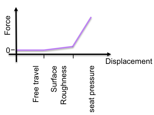
I) Identify the Load Case - Select the Load-Displacement Type which is Next to it.
II)Follow the Analysis to Deduce Piezo Stack Requirements. Study the Diagram for Load Cases and
III) Click on the red Hyperlink for Further Information


Spring Force Load
Spring-Mass Load