The linear constitutive equation of piezoelectricity describes a mechanically linear-elastic material with the superimposed effect of an electrically induced force. The piezoelectric force, in turn, is directly linearly related to the applied electric field. A piezo actuator is also a capacitor with the superimposed effect of an induced charge, which is linearly related to an applied force. The displacement of the piezo actuator is the electrically controlled deformation of a solid body. Once a voltage is applied to a piezoelectric actuator, piezoelectric forces act instantaneously within the solid body. As a result, it begins to deform until the load and the linear deformation forces of the piezoelectric solid body reach mechanical equilibrium.
No Load - Free Stroke
The displacement X of a piezo actuator is equal to the piezoelectric (charge) constant d d multiplied by the voltage U.
X₀= d·U
Piezo actuators utilize multiple thin layers, and the achievable displacement is the value of a single layer multiplied by the number of layers. The thickness of each layer is 100 µm, the voltage is 150 V, and the electric field strength ranges from 1 to 2 kV/mm.
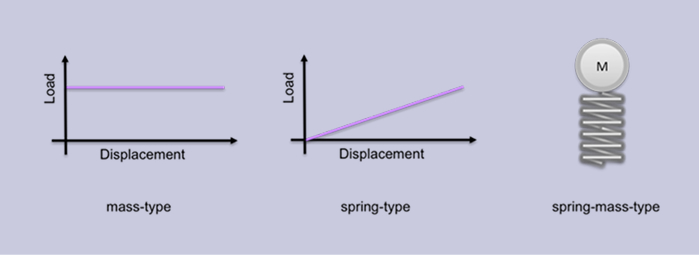
Weight Loading - Constant Load Force
T is constant. The displacement X of the actuator remains constant under a constant load force and is the product of the piezoelectric (charge) constant d and the voltage U. The gravitational force statically deforms the piezo actuator and overlays the electronically controlled deformation path of static deformation. This applies even when the external load forces are significantly lower than the blocking force.
Linear elastic load - spring type
The displacement of the actuator is reduced by the ratio of the stiffness of the load spring k load k load to the stiffness of the actuator ka.
X = X0 ka / (ka + kload)
free displacement X 0 = d ⋅ U X 0=d⋅U)
Blocked Actuator
The generated force is equal to the area multiplied by the piezoelectric constant d d multiplied by the electric field strength divided by the compliance s.
Fb = A d E / s
Abrupt Increase of Voltage
When the voltage source is abruptly switched on, the actuator experiences an impulse excitation. The electrical behavior of the actuator is that of a capacitor, drawing large currents. The amplifier provides maximum current until the voltage reaches the commanded final value after a rise time d T dT.
I =C · dU/dt
If the amplifier is capable of delivering high currents, the actuator may overshoot in this situation, posing a risk of internal tensile stresses. To prevent the risk of damaging an actuator, the following measures must be taken:
I) Current limiting is a reliable method to reduce the rise time and prevent damage due to overshoots.
II) A force biasing mechanism can be installed to compensate for the transient tensile stress in the piezo material during rapid acceleration.
Dynamic control of piezo actuators
In dynamic control, periodically varying voltages (sine or square waves) or non-periodic signals are applied to the actuator. An example is high-pressure fuel injectors in modern automobiles. They spray fuel very precisely into the combustion chamber. Piezo actuation is technically superior to electromagnets. A fuel injector driven by this technology can generate multiple fast and precise impulses during an engine's combustion cycle.
The dynamic behavior of a piezo actuator with coupled mechanical load is determined by masses, stiffnesses, and damping rates. The actuator itself represents a low-damping spring-mass system. The low-frequency displacement behavior of such a system is limited or given by the free displacement capability of the actuator. At higher frequencies, displacement is limited by the inertia of the effective actuator mass. The achievable displacement of an actuator in sinusoidal operation is determined by the balance between the piezoelectric force and the inertia force of the accelerated effective mass. The following equations illustrate the mechanical response far below and above the mechanical resonance frequency f r :
a) f ≪ fr X = d U
b) f ≪ fr X = Fb / (MLast (2 pi f) 2)
Highly dynamic operation of a piezoelectric actuator leads to outstanding mechanical (force x velocity) and electrical (voltage x current) performance values. However, piezoelectric materials are subject to damping effects, which result in losses and corresponding heating of the material during dynamic operation. Piezo stacks heat up quickly during continuous dynamic operation. It is essential to take sufficient measures to avoid reaching excessively high temperatures:
I) Limiting the amplitude (voltage, displacement),
II) The cutoff frequency,
III) Limiting operating time and
IV) Adequate Cooling
PIEZOTECHNIKS is your best choice in high performance and dynamics!
In the linear theory of the piezoelectric effect, a description of the small-signal behavior was developed (for further information see * 1 * 2). This theory does not include...
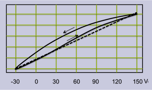
The real piezo actuator deviates significantly from a linear behavior in large-signal operation and the expansion shows a pronounced hysteresis behavior. There...
Piezoelectric actuators exhibit electrical behavior similar to capacitors. This behavior is overlaid with the piezoelectric effect, which couples mechanical and electrical...
This class of materials allows for the straightforward implementation of functions within load-bearing mechanical structures. While in artifacts such as machines or...
We use cookies to provide you with the best possible experience. They also allow us to analyze user behavior in order to constantly improve the website for you.